Repairing my first Solartron 7081
I purchased a Solartron/Schlumberger 7081 DVM at an auction in late 2008.
When I got it home, I wasn't greatly surprised to find that it didn't work! It powered on, but apart from a brief flash, the display didn't light up, it was unresponsive to key presses and the LED annunciators were not lit.
As the initial step I downloaded the manuals from Didier Juge's website, but these are now superceded by my own scans:
Solartron 7081 User ManualSolartron 7081/7071 Service Manual
and also ordered a photocopy of the service manual from Telford Electronics in the UK as I intended to keep the meter if I could get it working.
First steps
The first problem I noticed was that the memory backup battery on the Earthy CPU board was leaking, so I ordered a replacement from RS Components.
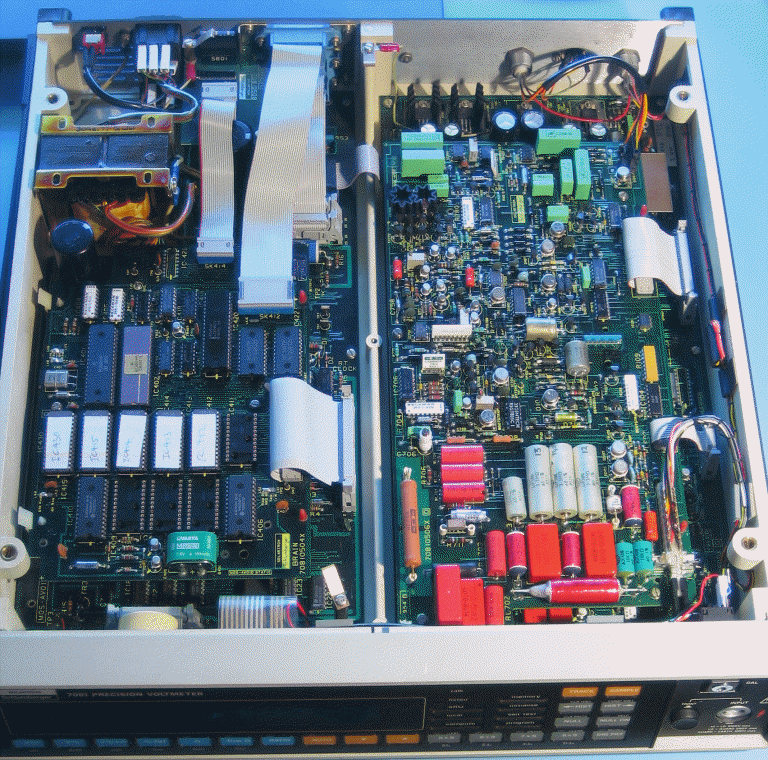
I initially checked the power supplies on the earthy and floating logic boards. The floating power supplies were all OK, but the +5V supply for the earthy logic was very low at about 3.6V and unstable, and the +40V supply was low but stable at 27V.
Access to the earthy logic board is obtained by removing the earthy processor board which is on top of the logic board.
Checking round the 5V supply soon showed that there wasn't any obvious problem with the unregulated supply, and that TR56, TR53, and TR54 all seemed to be working. The likely suspect appeared to be IC55 (TL494), and a replacement was ordered.
While diagnosing the power supply fault on the +5V supply, the meter did spring into life once, but refused to do so on the next power cycle.
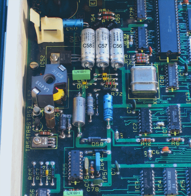
The 40V supply is a somewhat unusual configuration. The AC supply is connected to the bridge rectifier D55 via two voltage doubling capacitors C56 and C57. The rectified output is then smoothed by C58 and applied to the input pin of the 5V regulator IC52 (7805). A 30V zener D56 is connected between the 5V rail and the G input of the 7805. This supplies 35V which when added to the 5V supplied by IC52 gives the required 40V.
The fault with this supply was the voltage doubler capacitors C56 and C57. These were 47uF/40V (-10%, +50%) parts originally as was C58. The voltage rating on these was in my view a trifle low, so I ordered three low ESR 47uF/60V replacements.
Once these parts arrived, replacement was relatively simple, with the exception that removing IC55 proved to be a bit of a challenge because this is a multi-layer board of some vintage, and it seems that no thermal reliefs were used at that time on via connections to the inner planes. Once it was out I installed the replacement in a socket.
Power supply voltages were now as expected, but still no luck.
Now what?
No display output with no LED indicators lit suggests a fault on either the Earthy Logic board (PCB3) or the Earthy Processor board (PCB4). The most likely faults being ROM, RAM, CPU or DMA failure.
With the processor board disconnected, the power down reset is asserted by counter IC5. With the processor board installed, the counter is continually reset, which suggests to me that the processor is running.
Lots of further chasing round using a logic probe on the I/O board (with processor board connected), I found that pins 13-15 on IC17 on the earthy I/O board appear static which suggests to me that there is no DMA activity.
Here is what I saw at the processor.
1) The CPU crystal is singing away happily (pins 38/39)
2) Pin 34 has clock signal (E PIN).
3) NMI (pin 2) is high, BUT IRQ (pin 3) is LOW.
And at the DMA chip:
A) Pin 40 has a clock signal
B) Pin 2 ~CS is high
C) Pin 33 ~DEND is high
The interrupt handling is a priority interrupt scheme implemented using a 74LS148 on the earthy logic board, with the id of the interrupting device placed on the data bus by a 74LS367 gated by R$5000 which is derived from the address decode circuitry on the CPU board. Looking at the address decode lines on the 74LS138s on the processor board shows that the only I/O related address line being strobed is $4C00 (which is the reset signal for the watchdog timer and also the strobe for the keyboard read PIA).
All the logic that I checked on the earthy logic board appeared to be working normally, and the keyboard scan logic was sending the correct responses back to the PIA when the keypads on the front panel were pressed.
Phil Parsons kindly sent me a 68B09 processor and some 6264 RAM chips. I removed the original HM6117 (16kbit) RAM chips and re-worked the jumpers on the CPU board for the 6264 (64kbit) RAM chips, and replaced the CPU. This achieved precisely nothing, so I reinstalled the original CPU.
I worked round the CPU board checking for shorted or open bus lines, but found no problems, though the IC socket for the IC430 ROM chip had been poorly re-soldered at some stage. Unfortunately re-working this also achieved nothing.
Using a logic probe on the CPU address lines did show that A8 and A9 appeared to be logic low, but whether that was significant or not wasn't clear to me.
A cry for help
At this stage I was rather stuck. It seemed likely that the problem might be the ROMs but I wasn't able to prove that as I didn't have a ROM burner to check the existing ROMs. It turned out that Dave Baxter (one of the folks I had been email chatting with about fixing this) lived relatively locally and had a ROM reader/burner and previous experience of working on this type of microcontroller system. He very kindly came up to assist with the problem.
First of all the A8 and A9 lines on the processor being low to the logic probe was significant. The CPU address bus drivers were sick and the processor was running "toasty warm" to quote Dave. Some time was spent establishing that it was the CPU, and not the ROM/RAM chips causing this problem.
Replacing the CPU with the one that Phil Parsons sent me resolved that problem (many thanks Phil), but the system would still not boot up.
Dave then spent quite a bit of time checking what was going on round the keyboard PIA on the earthy I/O board: The PB0-PB3 lines from the 8291A to the '145 buffer were going up and down, but only from 0V to 1V +ve. Swapping the PIAs didn't change this. It is of course possible that both 8291As were fried, but I'd be surprised.
We also checked the RTC which is also connected to those lines, we *think* that it is not implicated right now, as removing it did not fix that problem.
At this point Dave had been here for quite a few hours, and it was nearly time for him to leave.
In the remaining time we removed the ROMs (all TMS2564) and read them. A few attempts at reading IC430 finally gave us a CRC16 checksum that matched the label on the IC, and we were able to verify the ROM image we'd grabbed. The other ROMS with the expection of IC414 read fine first time and gave checksums that matched the labels. IC414 unfortunately took a few times through to get a consistent checksum and that didn't match the checksum on the label at all, and furthermore, the text strings in the .bin file that we could identify were clearly garbled. The ROM images we grabbed don't match the images that Bill Ezell sent me.
A call for help on the mailing lists I subscribe to resulted in an offer from Alan Melia to try to read the iffy ROM on his Sunshine EPROM burner which he has had good experience with reading ROMs that wouldn't work in circuit. I therefore posted the suspect ROM to him.
A few days later I got an email from Alan saying that he'd successfully read the ROM and the checksum he'd got matched the checksum printed on the label (all the ROMs had non-original labels on, which suggests that the firmware had been updated somewhere along the way). He emailed me the image, and a visual inspection of the contents using a hex editor showed that the text strings looked sensible.
I then ordered a set of six TMS2564 ROM chips from Dial Electronics in the UK which turned up a couple of days later.
Success
Dave Baxter was next able to come up with the ROM burner a few days later on Friday the 8th of May.
Replacing just IC414 with a new TMS2564 burnt with the original image that Alan Melia was able to read didn't solve the problem. But replacing *all* the ROMs on the earthy processor board with the NOS ones I bought from Dial Electronics did. The meter sprang to life.
We also removed the ROM chip from the floating logic board and read that so that I had a complete set of ROM images for the meter.
The ROM images are here
Another piece of fine test equipment brought back from the grave and probably good for another 20 years service.
Notes on the ROM Images
The ROM images are in Intel binary format and are from an early 7081 (Serial Number 180) with 2564 ROMS.
The ROMS had been updated during the instruments life, and are
the largest ROM image set I have seen
for these meters. In IC412 (the highest addressed ROM)
the bulk of the content stops at 0FB9, there
is then a largeish area of all x'FF' with more code/data starting
at 1C00, and ending at 1EAD, and
finally starting at 1FD8, there is the string:
"VDD BSW 8 De 86 8 50"
followed by some more binary data to the high 1FFF address. The
string looks awfully like a compile
date and time. All the other ROM sets I have seen for
the earthy processer have '84 dates.
Update 22 December 2011: I just received an email from one of the engineers at Ametek (Solarton as was), and he confirms that the 2564 ROM images I have are revision code DD which is the final firmware release. They should work equally well in 2764 equipped 7081s as well, even though some differ slightly in checksum and content, the differences are trivial (as can be seen below).
The CRC16 checksums are:
IC430 3238
IC415 C5C0
IC414 1260
IC413 B958
IC412 ED50
The ROM on my floating logic board is also a 2564 and has also been updated.
The CRC16 checksum is:
IC803 8900
Most of the data in this ROM stops at 11ED, except that at the end, starting at 1FDA, is the string:
"VAF BSW 13 Fe 84 11 07"
followed by some more binary data to the high 1FFF address.
The dates and content of the ROM images from two other 7081s
fitted with 2764s for this ROM appear
to be the same, though the string reads: "VBA BSW 13 Fe 84 11 07".
Apart from that the only difference is in the first byte of the ROM image:
Comparing IC803.bin and 7081-51.BIN...
Compare error at OFFSET 0
file1 = 174
file2 = 178
Compare error at OFFSET 1FDB
file1 = 65
file2 = 66
Compare error at OFFSET 1FDC
file1 = 70
file2 = 65
Compare more files (Y/N) ? n
Likely the first byte is an 8-bit value to make the 8-bit
additive checksum come out with a value of
zero, as the difference in value of four matches up with the
differences in the other two bytes that
differ.
Repairing the second 7081
This meter was definitely going to be a challenge, for a start it had a label on the top indicating it was displaying "MAINS FAULT" followed by "WAIT @F". One of the ICL7650s from PCB 5 had been removed, and what's worse it wasn't very well packed by the person who sent it to me, with the result that the Noritake Itron FG209M2 display was broken (no vacuum). For the initial repairs I borrowed a display from a 7071 which I also had on hand.
Initial checks
The 7815 on the floating board had failed short circuit, with the result that the +15V rail was actually running at about +24V. C716 which was a 4.7uf 35V bead tantalum capacitor on the +15V rail had failed short circuit, and one of the leads had been cut - this was probably what caused the 7815 to die.
The wrong baud rate doesn't help
As the meter was reporting problems with the serial communication between the board, I put the Logic Analyser onto the serial signals. The first and most obvious problem was that the floating CPU was sending data at 300 baud, rather than 76800 baud even though the switches were set for the higher speed. This was a problem with the HD63A03 microcontroller. Luckily I had a 7150 from which I could steal the HD63A03RP (which is compatible).
MAINS FAULT
Replacement of the uC got rid of the WAIT @F, but the meter was still reporting MAINS FAULT. Using the Serial Analysis Tool on the HP 16700A I was able to decode the data streams. About 300mS or so after power on the floating side was sending 0x31, followed a few mS later by some other data. The 0x31 is the correct code for 50Hz operation. About 1.2 seconds after power on the earthy side sent a 0x00 to which the floating side replied 0xC6 which triggered the MAINS FAULT message.
At this point I spend quite a while with a great deal of assistance from Paul Flinders disassembling the startup portion of the floating ROM and also looking at the code that parsed the signals received from the earthy side. Eventually I worked out that the statement in section 3.2.4 of the service manual that says;
The floating side is pushed out of reset by a character sent from the earthy.
was not referring to a software initiated reset but to a reset fired by a watchdog timer which operates if nothing is received from the earthy side for more than 200mS. Replacing the faulty 74LS161 (IC827) used in this circuit meant that the uC was reset when the 0x00 was received from the earthy side and the MAINS FAULT error was cleared as the conversation now proceeded as expected. An interesting side note from this is that the mains frequency character sent is as follows:
| Character Sent |
Actual Frequency Range |
|---|---|
| 0x31 (50Hz) |
Less than 54.59Hz |
| 0x32 (60Hz) |
Between 54.59Hz and 228Hz |
| 0x33 (400Hz) |
Over 228Hz |
Unfortunately, clearing the "mains fault" error just revealed the next problem.
NVM FAIL
Oh dear, this is a bit serious, it means that the rather rare ER-3400 EAROM (an early type of EEPROM) which is used to hold all the calibration constants has failed which means a complete re-calibration will be required once the ER-3400 has been replaced. It was time to put out feelers to find one of these ICs and also to hunt for a display tube.
Much to my very pleasant surprise, a few weeks later, the postman delivered a packet containing a "New Old Stock" Noritake Itron FG209C2 VFD and an ER-3400 IC. My heartfelt thanks to the kind person who sent it, as both of these parts are very hard to find.
I installed the parts in pretty short order and needed to start the re-calibration of the meter the with all important "Calibrate,zener" command. This sets the current level for the reference zener diode, and the value for it was determined at the factory by temperature and current cycling each diode in an environmental chamber and recording its behaviour. Luckily Solartron put a small label on the lower right hand PCB (board 5) at the back of the meter near the right hand wall, which recorded the value for this all important calibration constant. As I had DC voltages up to 1000V and another 7081 I was able to calibrate the DC ranges fairly easily once the meter had been on for a couple of days.
Problems with the AC ranges
Attempting to calibrate the AC 0.1V range showed weird results, initially the readings after the calibrate command completed would be close to the value, but rapidly drifted off. Mickle Timofeyev suggested to me that it might be the same problem he reported on September 11, 2011 on the Volt-Nuts mailing list. In his particular case board leakage between the -10V and -15V pins of RL704 and the unguarded signal pin between them which is in a high impedance circuit (R723, 22MOhm) resulted in a high, temperature dependent reading in AC mode with the input shorted.
I checked my meter and it too was showing the same problem. I then checked with the guy I got the meter from who confirmed it had been stored by its previous owner in a cold, damp garage for a lengthy period. I tried the "warm-up" procedure described on page 2-3 of the User Manual, which effectively "cooks" the meter in its own juices (so to speak). Looking at the AC zero offset (with the input shorted) clearly showed that there was problem, and that it was getting worse as the meter warmed up.
After about 18 hours of "cooking" the meter stopped working with the display stuck at a zero offest of 39mV! Luckily this was a simple problem to find: A tantalum bead capacitor in the -15V floating circuit decided it couldn't stand the heat and had left the kitchen (failed short circuit), taking the 7915 regulator with it. While I was waiting for a replacement 7915 to be delivered, I gave both sides of the PCB in the area of RL704, D712, and D713 a thorough clean up:
- Freeze spray to kill any bacterial contamination on the surface of
the board.
Sony had with a problem with a high-impedance circuit back in the seventies.   The problem began showing-up in older units
after years of use.   Technicians were able to temporarily eliminate the electrical leakage currents by spraying the area with
PCB cleaner solutions.   But the problem would return in a few months.   Finally Sony determined the problem was caused by
bacterial growth in higher humidity environments due to a contamination problem at the factory when the products were made.

Interestingly, Sony then released a Service Note, recommending that you spray the area with super-cold Freon to kill the
bacteria by freezing it. - Scrub with Ambersil N.F. Precision Cleaner (30-60% tetraflouroethane, 10-30% 1,1,1,3,3-pentaflourobutane).
- Scrub and rinse off with IPA
- Hot air dry.
Unfortunately this didn't help. I then spent quite a lot of time re-wiring the circuitry around the relays using PTFE feed-through insulators and direct point to point wiring in an attempt to eliminate the leakage problems referred to above. This helped a bit, and delayed the onset of the drift by a good five to ten minutes or so, but didn't fix it.
Finally, in desperation, I removed the upper floating board from the
meter, and stuck it in the oven, slowly increasing the temperature to
120C, and then letting it cook for six hours!!! There was
a small problem caused by doing this, as two 150pF polystyrene
capacitors melted (oops), and I had to order replacements.
That problem aside, to my pleasant surprise, this appears to have had
the desired effect in that the meter is now much more stable.
How is the 7081 different from the 7071?
The answer is that it is about 0.25 gram lighter as that's the approximate weight of solder that is used to short out LK17 on the earthy logic board. When this link is shorted, pin 2 of IC424 is pulled to ground and this is what tells the firmware that the meter is a 7071 rather than a 7081. The schematics show that this pin is connected to the "Interface" position of SW801 (position 8) which you might think was to enable or disable the GPIB support. On the prototype meters and many production meters, this switch was connected to pin 2 of IC424 which meant they could be switched from 7071 to 7081 mode by flicking this switch and re-initialising the meter. On some late production meters, this position of the switch was not connected to anything. The GPIB support is always enabled.
However just removing this solder bridge (or flipping the switch) won't magically turn your 7071 into a 7081, as the most important difference is one that you can't see. The reference zener diodes were soaked for several weeks in an oven which temperature cycled them and each diode was checked regularly for stability. The very best ones were selected to go in the tighter specified 7081. The not so good ones went in the 7071.
The only other difference is the labelling on the front panel buttons.
Solartron Meter ROM Images
Solartron 7150 ROMs.zipSolartron 7150 Plus ROMs.zip
Solartron 7151 ROMs.zip
Solartron 7071 and 7081 ROMs.zip
New Scan of Service Manual
I was recently able to borrow a very good copy of Issue 5 (August 1986) of the Solartron 7081/7071 Service Manual, which I believe to be the final version. I have now scanned this. It has been extensively cleaned up and combines data from the final revision of the manual plus selected information from other sources. It is scanned DUPLEX including schematics. Most of the document is A4 portrait, while the schematics are A3 landscape. I have made numerous annotations and corrections, particularly to errors in the schematics. The whole document with the exception of the schematics has been OCRed.The AC Linearity Modification (a change made to later meters) details are included on the AC RMS Converter Schematic.
Schematics for both the 2564 version (board 70817504) and 2764 version (board 70817514) of the Earthy Processor board are included.
Solartron 7081/7071 Service Manual
I have also added a copy of the user manual (July 2017) an optimised and OCRed scan of the User Manual
Solartron 7081 User Manual
Test and Calibration Procedures
The service manual contains a partial guide to the setup, testing and calibration of these meters, but the factory test and calibration procedure documents have a lot more detail. It is interesting to note that they actually took weeks to pass through the calibration stage, especially every tenth unit which was kept back and rechecked at 8 weeks and 13 weeks.
Here is a scan of the document with the full factory setup, test and calibration procedures for the 7071 and 7081 meters.
Solartron_7081_Test_Spec.pdfUnfortunately it doesn't contain the source code for the calibration programs which I believe were run on a Commodore PET, but I hope it is nonetheless of some use.
Replacement Earthy Processor Board
Sometime around 2020, I acquired a 7071 with a faulty "Brain" or
"Earthy Processor" board. I spent ages trying to fix it and in
the end I just gave up on it, until I saw a topic on EEVBLOG started
by Lucas Spitzkopf:
https://www.eevblog.com/forum/repair/solartron-7081-earthy-processor-board-reverse-engineering
describing a two layer replacement PCB he had created for this.
This inspired me to create a four layer replacement board based upon his KiCad schematic:
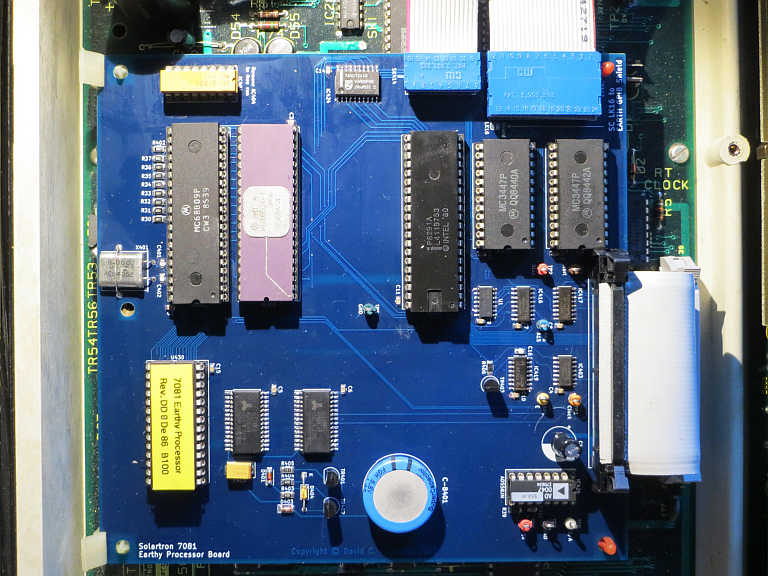
This worked well and the KiCad project is here: Solartron-Earthy-Processor-master.zip
You can also download it from GitHub:
https://github.com/perdrix52/Solartron-7081-Earthy-Processor
I have few bare boards for this available for £25 each, and a few programmed OTP EPROMS for £7.50 each (plus postage and customs charges if appropriate). Please email me if you are interested.
