A replacement levelling head for the Tektronix SG504
Ordering
You can order the kit by emailing me. The cost is GBP80 including shipping. If you live in the UK, then I don't pay so much postage, so I only charge GBP72.50. I apologise for this increase, but I can't subsidise the recent increases in international shipping charges and component prices any more.
Introduction
The Tektronix SG504 is a levelled sine wave generator that covers the frequency range 245MHz to 1050MHz in two bands. It uses an external levelling head part number 015-0282-00. The SG504 is frequently seen for sale, but more often than not without the necessary levelling head. The levelling heads very rarely appear for sale, and often command very high prices or don’t work properly.
I decided that there must be a market for a kit to replace the “guts” of a failed levelling head, or to allow a complete replacement to be constructed using a suitable housing.
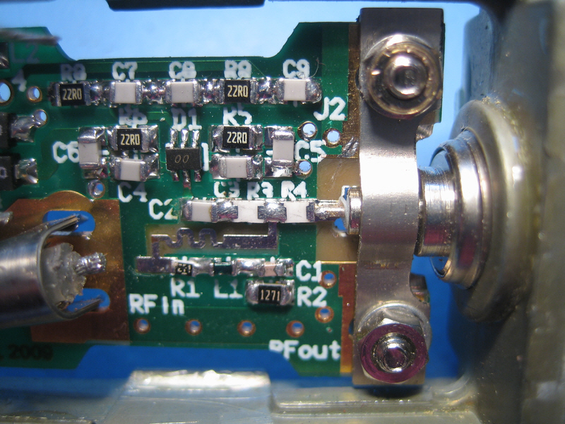
I therefore completely disassembled a failed levelling head and reverse engineered the circuit. The original levelling head was constructed partially on standard fibreglass PCB substrate, and partially on a 40 mil thick hybrid, as may be seen from the photograph below:
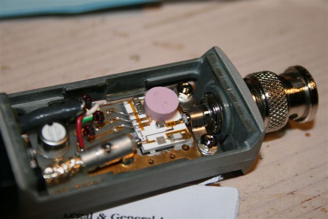
The basic design is an RF power splitter, and a voltage doubler peak detector. The diodes for the detector are under the pink isothermal cover at the top right of the hybrid, as are the reference diodes and a few other components.
As I don’t have access to a hybrid fabrication plant, I decided that I would design the replacement PCB using surface mount components on a double sided 0.8mm thick PCB. The only concern was whether standard FR4 substrate would do the job, or whether it would be necessary to use an “exotic” (read expensive) substrate like Rogers 4350B. Extensive RF simulation of the crucial parts of the PCB design using Ansoft Designer SV indicated that there should not be a problem with using FR4.
The obvious choice for the detector diodes seemed the Avago Technologies HSMS-282x range. I eventually decided to use the uncommitted Ring Quad HSMS-282R, as this would ensure better thermal tracking between the reference diode pair and the detector diode pair. A possible alternative would have been to use two HSMS-282K, or two HSMS-282C, but the latter offered no advantage and used more board space, while for the power levels involved (-1dBm to +19dBm), the balance seemed to favour the use of the HSMS-282R. This was confirmed by Avago Technologies technical support.
Construction notes
Apart from a collection of parts, you will have a PCB. Here is what the PCB you get looks like:
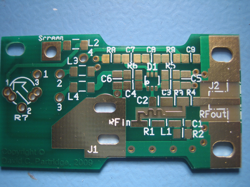
The PCB is designed to be used either in your own case; or in the original Tektronix housing (if you have a dead levelling head). To use it in your own case I have provided pads for an SMA bulkhead end launcher at the right hand side. In this case, as well as the SMA end launcher you will need an SMA male to BNC male adapter.
If you are going to use this in the original Tektronix levelling head housing, you will need to cut out the area that is partially marked in silk screen on the RHS of the PCB. My apologies it is not as clearly marked as intended, the fabrication plant decided they didn’t like silk-screen on bare copper and removed the dashes, but thankfully left the dots!
The parts kit only contains the PCB, the surface mount components, some of which were fairly hard to source (in the UK at least), and the 1kOhm trim-pot (R7). It does not include cables or connectors. A suitable Lemo connector is the FFA.0S.304.CLAC42 or FFA.0S.304.CLAC44. You can buy the latter from RS Components in the UK http://uk.rs-online.com/web/p/circular/1732039/
To construct the board, you’ll need a fine tipped soldering iron, some very fine solder, and liquid SMT rework flux. I strongly suggest that you install the detector diode first, and work out from there. It doesn’t matter which way round the detector diode is mounted by the way, which helps a lot as pin one isn’t marked!
You may find it advantageous to use a very small dab of acrylic PCB lacquer to secure the diode and 0603 sized parts before soldering them. If you haven’t any previous experience of SMT soldering I suggest you look at the video tutorial entitled Surface Mount Soldering 101 which you will find at:
http://www.curiousinventor.com/guides/Surface_Mount_Soldering/101Here’s what the prototype board looked like with all the components installed and the cut-out for mounting in the original Tektronix housing:
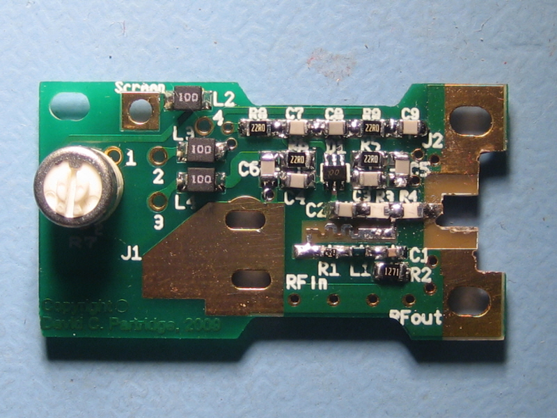
I hope you make a tidier job of the cut-out than I did!
You should notice that the 50 Ohm (strictly 49.9 Ohm) resistors R3 and R4 which make up the power splitter are mounted face down. This was done deliberately to minimise stray inductance.
Mounting the PCB in the Original Housing
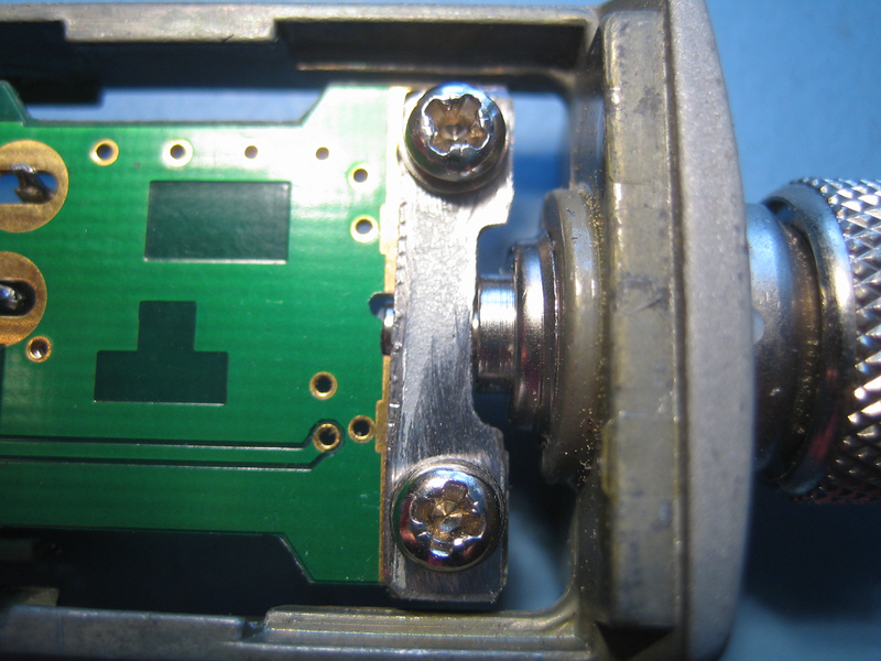
To mount the head in the original housing you’ll need to do two things – one is to slightly flatten the bridge section of the clamp that goes over the BNC output connector because the replacement PCB is slightly thinner than the hybrid that is mounted on the original PCB. You will also need to make up a flat metal clamp piece to go underneath it:
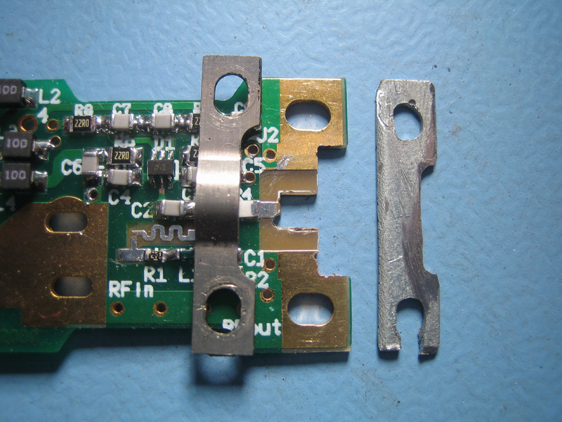
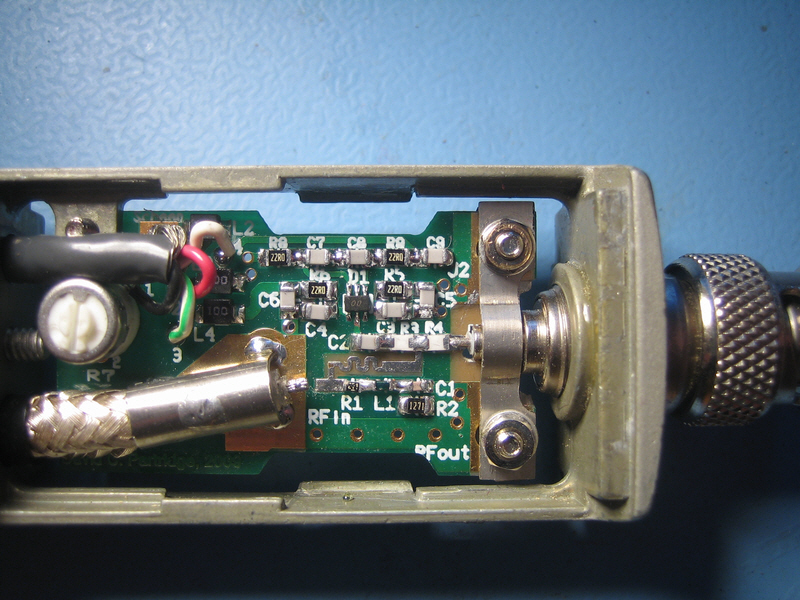
Once that is done, you can mount the PCB in the housing:
All that remains is to connect the 4 core cable to connection points 1 to 4, solder the input coax screen and use a fine wire to connect the centre core of the input coax to the pad next to R1, and finally to solder the centre connector of the output connector:
And here’s the finished product:
Calibrating the Head
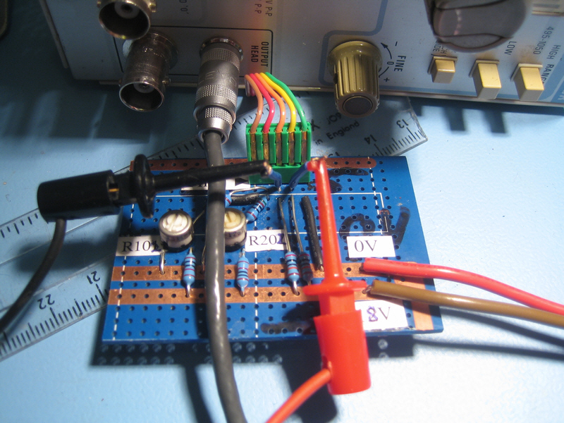
The trim-pot (R7) is used to calibrate the head for mismatches between the detector and reference diodes. In theory the HSMS-282R diodes are sufficiently well matched that I could have substituted a pair of 510 resistors for the trim-pot, but I decided to retain the same design in this respect as the original levelling head. The calibration circuit is quite simple, and the schematic is at the end of the document. I made it up on a piece of stripboard.
The way I connected the calibrator to the head was to plug the head into the SG504, and carefully bring out the ribbon cable and five way connector from the SG504 to the five way header on the calibrator board (Do be very careful doing this, I know to my cost who easy it is to break the wires at the back of the Lemo connector):
The first thing you will need to do is connect the calibrator to a lab PSU set for 18.00V (make sure you get the polarity the correct way round). Then there is a “one time action” to calibrate the calibrator which involves adjusting R102 and R202 as described on the schematic page.
Once you’ve done that, you connect your voltmeter as shown and adjust R7 in the levelling head for lowest possible voltage between pin 3 and pin 4 (<1mV or better).
Once you’ve put the SG504 back together, there is a final step that needs to be taken. You must re-adjust R280 and R270 in the SG504 according to the instructions in Step 7 Adjust Reference Amplitude at 0.05MHz on page 3-6 of the SG504 manual. You should also check that the 6MHz output levels are correct.
Flatness results with the prototype head
Here is a spreadsheet with a graph showing the actual output level of the substitute levelling head at three different output levels across the entire band of the SG504: Calibration Data SpreadsheetAs you can see the worst case deviation of the output is [+0%, -2%] which is within the specifications of [+3%, -3%] as set by Tektronix, and only very marginally less good than my original head after I had adjusted the trim-pot.
